Sheet Metal Design for Manufacturing: 10 Mistakes That Increase Fabrication Costs
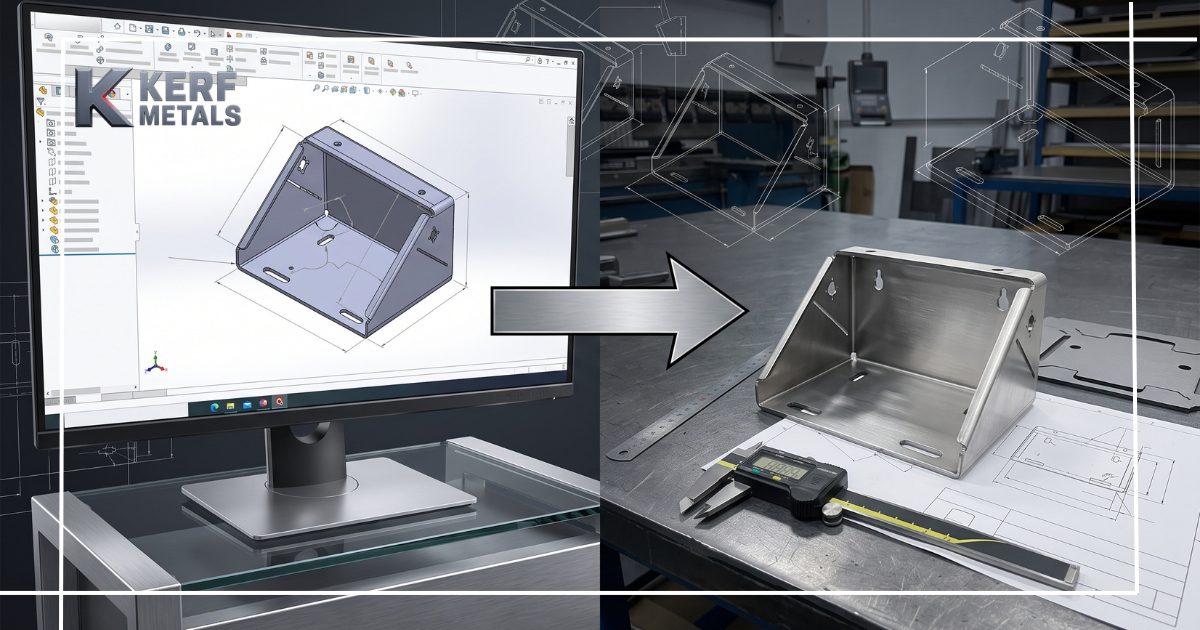
A sheet metal part can look perfect in CAD and still be unnecessarily expensive to manufacture.
That gap between digital geometry and real-world fabrication is where many avoidable costs begin. Once a design reaches laser cutting and forming, seemingly minor decisions about tolerances, hole placement, bend radius, material, and part geometry can translate into additional setups, slower production, scrap, rework, or secondary operations.
Design for Manufacturing (DFM) helps prevent those problems before production begins.
Here are ten common sheet metal design mistakes that can increase fabrication costs – and what to consider instead.
1. Applying Tight Tolerances Everywhere
Not every dimension needs machining-level precision.
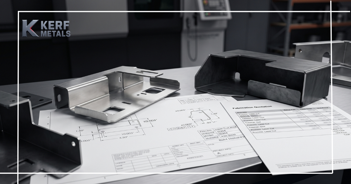
Sheet metal changes during bending as the material stretches and compresses. Applying unnecessarily tight tolerances across an entire drawing can require additional inspection, setup adjustments, or secondary operations.
Instead, identify the dimensions that genuinely affect fit, function, or assembly and apply tighter tolerances only where necessary.
DFM takeaway: Precision should be intentional, not automatic.
2. Ignoring Material Behavior During Bending
Two materials with similar thicknesses can behave very differently in a press brake.
Strength, ductility, temper, grain direction, and thickness all influence how successfully a part can be formed. Selecting material based only on strength, appearance, or price can therefore create problems later.
Material selection should consider both the finished application and the fabrication process required to produce it.
3. Designing Bend Radius That Are Too Tight
Extremely small inside bend radius may look cleaner in CAD, but they can increase forming difficulty and the risk of cracking or distortion.
A practical bend radius gives the material room to form predictably and can also allow the fabricator to use standard tooling rather than specialized setups.
Whenever possible, use consistent, fabrication-friendly bend radius throughout the part.
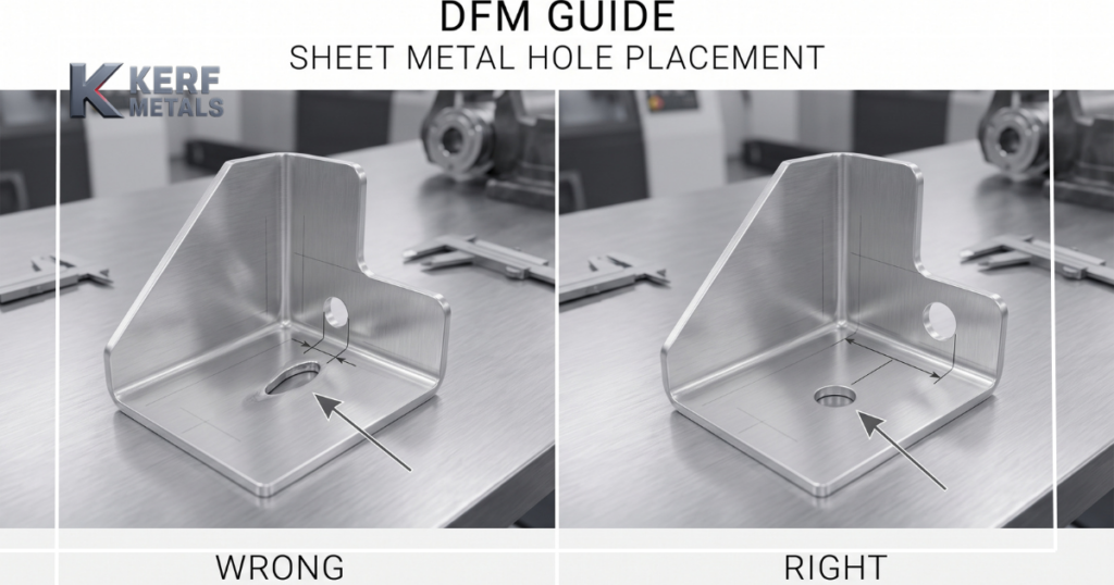
4. Placing Holes Too Close to Bend Lines
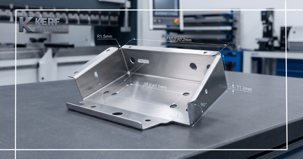
A perfectly round laser-cut hole does not necessarily remain round after bending.
Features positioned inside the bend deformation zone can stretch or distort as the material forms. This can affect holes, slots, tabs, and nearby edges.
The result may be poor assembly fit or a flat pattern that needs redesigning after the first article.
Better approach: Give critical features sufficient clearance from bend areas before releasing the CAD file.
5. Creating Unnecessary Bend Complexity
Every additional bend introduces another operation.
A part with six bends may technically work, but if the same function can be achieved with four, the simpler design can reduce machine time, handling, setup requirements, and tolerance accumulation.
Look at the complete geometry and ask whether each bend contributes something necessary to the function of the component.
6. Ignoring Tool Access
A bend can be geometrically possible while still being difficult to manufacture.
Deep flanges, enclosed features, return bends, and closely spaced forms can interfere with press brake tooling or prevent the part from being positioned correctly.
Thinking about the bending sequence early helps prevent designs that require unusual tooling or multiple additional setups.
Kerf Metals combines laser cutting and precision metal bending, allowing these manufacturing considerations to be evaluated as part of the same fabrication workflow.
7. Forgetting About Finishing
Powder coating, plating, and other surface treatments should not be treated purely as cosmetic decisions.
A finish can affect clearances, holes, mating surfaces, hardware locations, and final assembly.
If two components already have extremely tight clearance before finishing, coating buildup can turn the intended fit into interference.
Define the finish early enough that the geometry can accommodate it.
8. Using Too Many Unique Features
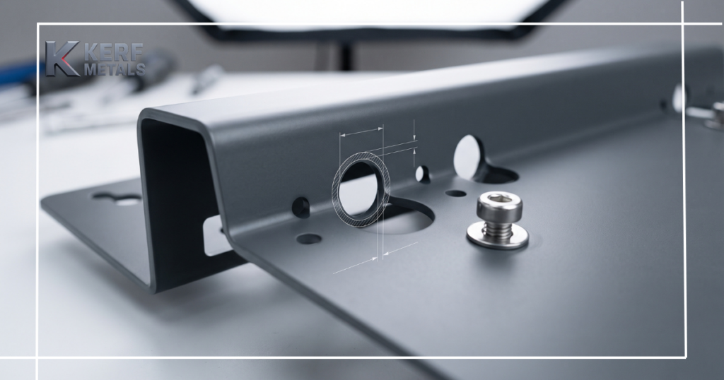
Designers sometimes create several different hole sizes, radius, bend angles, slots, and fastener types when standardization would work just as well.
Each unique feature can add programming, inspection, tooling, inventory, or assembly complexity.
Standardizing features wherever practical makes parts easier to produce repeatedly – particularly as production volume increases.
9. Sending Overly Complex CAD Files
A fabrication-ready model should clearly communicate what needs to be manufactured.
Complete assemblies filled with unrelated hardware, electronics, purchased components, or unnecessary geometry can slow down file preparation and quoting.
Before sending files, suppress anything that is not relevant to the fabricated component and clearly identify material, thickness, quantity, and critical specifications.
Kerf Metals accepts CAD and project files including DXF, STEP and PDF, which can be reviewed before fabrication begins.
10. Waiting Until Production to Discuss Manufacturability
Possibly the most expensive DFM mistake is discovering a design problem after material has already been cut.
Changing a radius or moving a hole in CAD takes minutes. Making the same discovery after laser cutting, bending, or rolling has begun can mean new material, new programming, additional setup, and lost production time.
Early fabrication input can often identify these issues before they become costs.
Design for the Process, Not Just the Screen
Good sheet metal design is not simply about creating geometry that can be manufactured. It is about creating geometry that can be manufactured predictably, repeatedly, and efficiently.
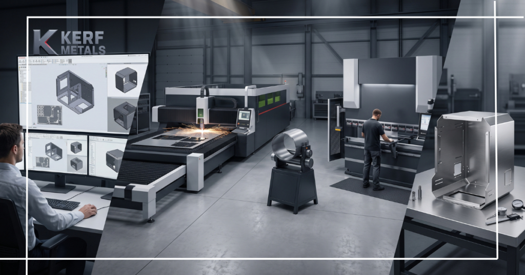
Kerf Metals supports projects from CAD files through laser cutting, metal bending, and metal rolling, helping manufacturers reduce the handoffs that can complicate production.
Before releasing your next sheet metal design, review the tolerances, material, bends, hole locations, tooling access, finishing requirements, and overall complexity.
A few changes before production can prevent considerably more expensive changes afterward.
Have a sheet metal part ready for production? Upload your drawings to Kerf Metals and get a fabrication quote for your next project.