Prototype to Production: How to Scale Sheet Metal Parts Without Expensive Redesign
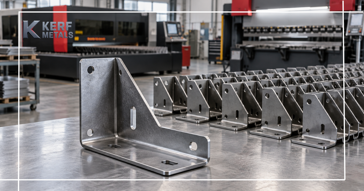
Getting a one-off sheet metal prototype right is satisfying. But holding a part that looks and fits great on the bench only proves one thing: it worked once. The real test is whether you can churn out fifty, five hundred, or five thousand of them without the job turning into a budget trap.
Too often, the tribal knowledge used to make that first sample work – a tech filing down an edge, a press brake operator giving an extra nudge by hand – stays on the shop floor. When volume ramps up, those unwritten tweaks quickly morph into costly scrap and missed deadlines.
The cheapest time to fix a production headache is before the initial prototype sign-off. When you map out the entire fabrication sequence early, lock down your revision history, and test components under actual assembly line conditions, scaling into repeat runs feels routine rather than risky.
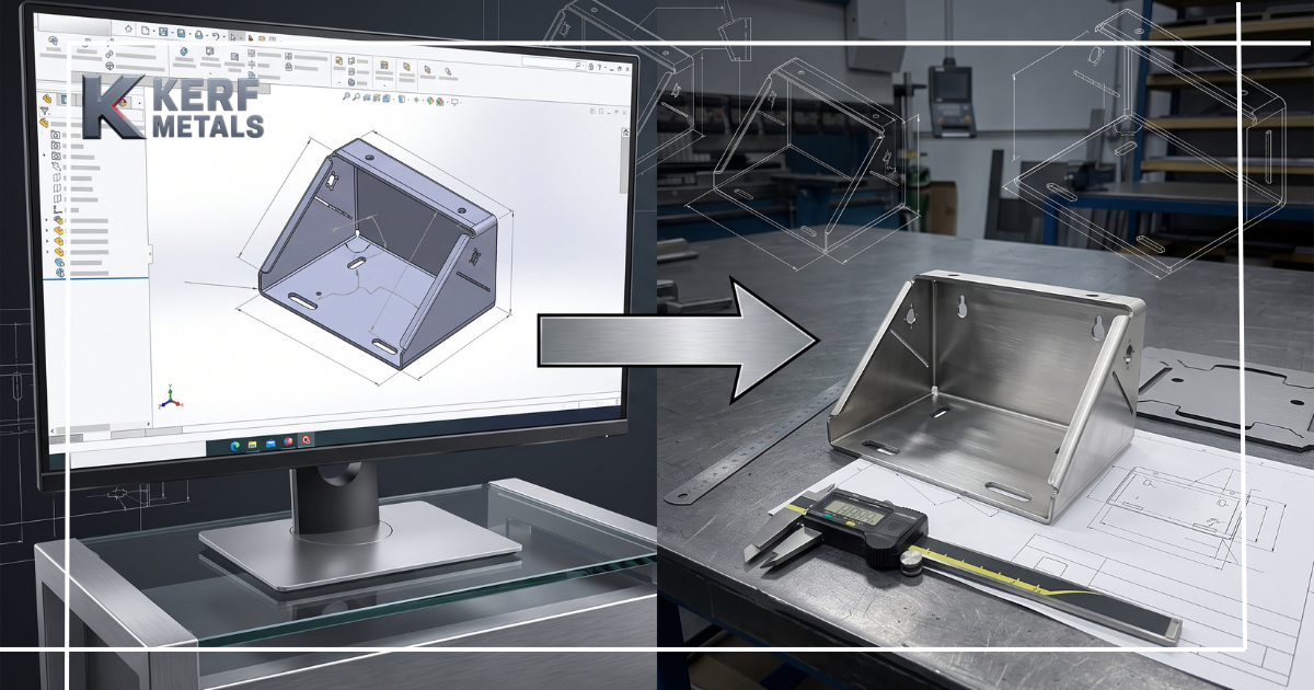
At Kerf Metals in Middlesex, New Jersey, we bridge that gap with precision laser cutting, forming, and plate rolling. The objective is straightforward: take your CAD files and technical drawings and establish a repeatable, stable production baseline that scales cleanly as demand grows.
Why a Working Prototype Can Still Flop on the Line
A single prototype is forgiving. An experienced assembler can deburr a stubborn edge, tweak a flange with pliers, or tap a fastener into place. That extra five minutes of elbow grease barely registers on a quantity of one. Multiply it across a batch of 250, though, and you are suddenly eating massive labor overruns.
Parts usually run into trouble during scale-up because the original design package left too much open to interpretation. Common culprits include:
Unmarked critical dimensions: When an operator doesn’t know which features dictate mating fit, they might hold the wrong dimension tight while letting the crucial one drift.
Holes sitting right on the bend line: If an opening sits inside the bend’s deformation zone, it will stretch into an egg shape during forming.
Geometry that hates the laser: Micro-slots, razor-thin webbings, and tight internal corners that burn out, overheat, or warp during cutting.
Flanges with zero clearance: Bends placed too close to existing cutouts or edges, causing distorted metal or tool collision against the brake tooling.
Vague material specs: Calling out “16-gauge aluminum” instead of specifying 5052-H32 vs. 6061-T6. They bend completely differently.
Missing bend orientation or radius: Leaving the inside bend radius or grain direction up to the operator’s preference.
The “lost revision” trap: Testing a tweaked prototype on the bench, but forgetting to update the master CAD file before issuing the production PO.
Ghost secondary ops: Drilling out a hole or deburring a flange by hand on the bench, but never putting that step onto the official print.
None of this means your prototype was built wrong. It just means the process relied on human guesswork rather than explicit instructions. Reliable production requires that the 3D model, the 2D flat layout, the print notes, and the physical material all align perfectly.
Start With a Production Intent Review
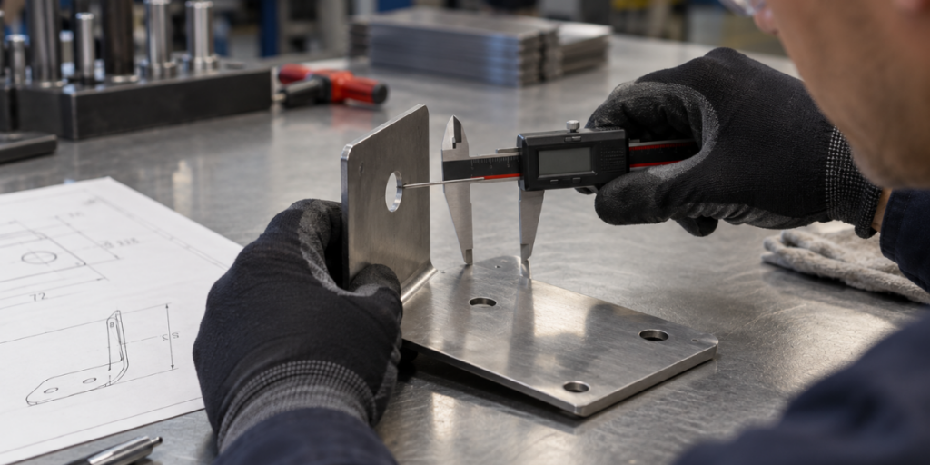
Before you send out RFQs for a prototype, take an afternoon to nail down how the part functions and how quality will measure it. While a qualified fabricator will flag obvious clearance clashes or tooling limitations, the engineer owns the functional spec. The cleaner your input package, the sharper and more helpful your supplier’s feedback will be.
A solid prototype handoff package should include:
Native CAD and flats: Clean STEP models alongside 1:1 DXFs and a fully dimensioned PDF drawing.
Specific material callouts: Exact alloy, temper, thickness, and any surface treatments required.
Volume projections: Quantity for the initial build alongside realistic monthly or annual production forecasts.
Inspection targets: Critical-to-function dimensions, dates, and specific inspection features clearly flagged.
Forming specs: Specified inside bend radious, bend directions, angles, and final envelope dimensions.
Cosmetic expectations: Grain direction, cosmetic face callouts, deburring standards, or protective masking needs.
Downstream reality: Welding callouts, clinch hardware, powder coating build-up allowances, or final packaging specs.
Logistics: Delivery expectations, dock requirements, and required turnaround dates.
Giving your shop this complete picture lets them look at the job as an interconnected manufacturing path rather than three disconnected operations on a floor.
Seven Steps to Scale Sheet Metal Components Smoothly
1. Design for the Real Manufacturing Sequence
A flat blank only tells a fraction of the story. If a bracket gets laser cut and then tossed into a press brake, the geometry has to survive both steps without conflict. If it gets rolled into a cylinder, the alloy, thickness, and grain direction must support that specific radius without cracking or flat-spotting at the ends.
Walk through the sequence feature by feature. A hole might cut cleanly on the laser, but if it sits inside the die shoulder during forming, it will pull out of round. A tab might slide into its slot easily on the 3D screen, but once powder coat adds 3 to 5 mils of thickness, it jams. Think about how the part flows from pallet to laser to brake to finish.
2. Lock Down Production-Grade Stock Upfront
Prototyping with whatever drop or scrap is lying around the shop floor is tempting. It is also risky. Mild steel, 304 stainless, 5052 aluminum, and galvanized sheet behave radically differently under a brake punch.
Even within the same alloy family, temper and gauge tolerance dictate springback and bend deduction. If you qualify a part using soft, forgiving scrap, you might find the production batch cracking or under-bending when hard structural sheet arrives. Validate with the real thing from day one.
3. Target Critical Features—Don’t Over-Tolerance the Entire Print
Slapping a blanket block tolerance across every single dimension on a sheet metal drawing is an easy way to quadruple your part cost without gaining any performance. Sheet metal is inherently flexible.
Reserve tight tolerances for mounting holes, bearing pockets, slide alignments, and safety-critical interfaces. Give generous breathing room to overall panel lengths, decorative flanges, and non-mating reliefs.
Always tie critical mounting holes to a shared functional datum rather than stringing a long chain of dimensions edge-to-edge. Tolerance stack-up will ruin an assembly faster than almost anything else.
4. Beat Up the Prototype in Its Real Working Environment
Don’t just measure the part on a granite surface plate and call it done. Bolt it into the full assembly. Does the technician have enough clearance to get an impact driver onto the fasteners? Do the harness cutouts align once the mating frame is torqued down?
If the final product gets powder-coated, exposed to engine heat, or vibrated on a truck chassis, run your prototypes through those exact environments. Keep an open log of every snag. Separate actual geometry tweaks from minor fabrication notes so everyone understands what needs a CAD update and what simply needs a shop note.
5. Enforce Strict Revision Control
Never let a part go into volume production when the file is named Bracket_Rev2_final_v3_NEW.step. That is asking for a wrong cut.
Use explicit revision letters or numbers across every drawing, DXF, and 3D model. When a change happens, update the drawing title block, revise the cut file, and archive the old version out of reach. When sending an updated package to your fabricator, include a quick bulleted changelog. Clear version tracking eliminates the heartbreak of opening a crate of 500 parts cut to an obsolete revision.
6. Run a Pilot Batch Before Opening the Floodgates
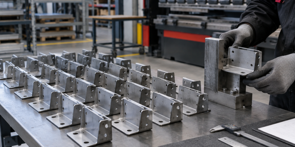
If a part involves multi-stage bending, rolling, or tight tolerances, jumping straight from one prototype to thousands is a gamble. A short pilot run-say, 15 to 50 pieces – is where you uncover the real production snags.
A pilot reveals things one part hides: minor tooling marks on cosmetic faces, slight nesting distortions across a full sheet of metal, packaging scratch hazards, and variation between different material heats. Treat this small batch with the exact same inspection rigors planned for full volume.
7. Freeze the Baseline Once It Works
When the pilot batch sails through inspection and fits into final assembly without filing or forcing, lock it down.
Archive the approved CAD models, the flat pattern files, the press brake tooling choices, and the inspection criteria into a controlled package. This is your manufacturing baseline. If you later swap suppliers, switch coating vendors, or change gauges, treat it as a formal change review instead of assuming the old rules will carry over on their own.

How Kerf Metals Handles the Prototype-to-Production Pipeline
Operating out of our Middlesex, New Jersey facility, Kerf Metals specializes in turning customer-supplied CAD files into clean, accurate components. Depending on what your project demands, we handle standalone processes or run parts through a coordinated sequence:
Precision Laser Cutting: Clean edge quality, tight contours, intricate cutouts, and dependable repeat accuracy across sheet and plate.
CNC Metal Bending: Consistent angles, controlled radii, and reliable flange heights for brackets, enclosures, structural channels, and chassis.
Plate & Sheet Rolling: Rolling smooth cylinders, pipe sections, curved architectural panels, rings, and sweeping radius forms.
Having one shop handle the laser, brake, and rolling keeps your project under one roof. It cuts out the finger-pointing that happens when a cutting shop blames a forming shop for a bad bend, or vice versa.
We work daily with standard file formats like DXF, STEP, and PDF, processing carbon steel, stainless steel, aluminum, and galvanized stock across varied gauges. Our estimators and shop leads review your submitted drawings for real-world manufacturability – checking for bend reliefs, hole-to-bend spacing, and edge proximity before we cut metal. You maintain full ownership of your engineering; we ensure the path through the machines is clean.
Building an RFQ Package That Prevents Redesigns
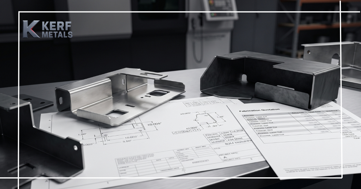
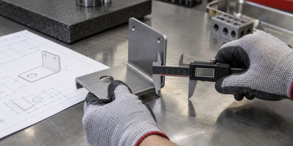
A complete quote request allows an estimator to give you firm numbers, spot potential tooling conflicts, and evaluate real shop floor risk before purchasing material.
When submitting an RFQ, include:
A 3D model (STEP) and a fully dimensioned 2D print (PDF).
A flat pattern (DXF) if available.
The specific material alloy, grade, and thickness.
The initial prototype quantity alongside anticipated batch sizes.
Clear callouts on critical mating tolerances and datums.
Notes on cosmetic faces, grain orientation, deburring standards, or post-finishes.
Target ship dates and delivery requirements.
A clear note stating whether the job is an exploratory prototype, a pilot run, or a frozen repeat build.
For complete packages, Kerf Metals typically turns quotes around within 24 hours. Lead times depend on material sourcing, geometry complexity, and whether secondary forming or rolling is involved.
Frequently Asked Questions
Yes, provided the prototype CAD matches what was actually built, formed, and tested. If you tweaked a flange on the bench or opened up a slot during fit-up, those changes must be pushed back into the master 3D model and 2D drawing before you release the production purchase order.
A single prototype proves concept and basic fit. A pilot run (typically 10 to 50 pieces) proves repeatability, reveals tolerance accumulation across multiple parts, tests handling and packaging, and lets your assembly team build at standard speed. If the part is complex or the volume run is high, a pilot run is cheap insurance.
Loosen non-critical tolerances, ensure hole locations don't require special secondary drilling operations, design flanges around standard tooling widths and bend radii, and consolidate orders into larger material sheet nests. Talk to your fabricator early—they can often point out minor layout adjustments that shave cutting time or simplify a brake setup without compromising part function.
Our focus is on precision cutting, forming, and rolling from customer CAD data. We supply precision components directly to manufacturers, OEM production lines, fabricators, and job shops who handle their own in-house welding, finishing, coating, and assembly.
Move Into Production With Zero Surprises
Scaling up sheet metal components shouldn’t require a frantic round of emergency redesigns. When you design around actual forming sequences, choose the right alloys upfront, control your revisions, and verify your parts in the real assembly, moving from part one to part five thousand goes smoothly.
If you have a fresh concept, an updated revision, or a repeat production part ready to run, reach out to the Kerf Metals team in Middlesex, NJ. Upload your drawings, let us know your volume targets, and we’ll turn around an actionable, competitive quote for your laser cutting, bending, and rolling requirements.